

Solar cable used on the DC side of a photovoltaic system is normally a flexible, single-core cable with a tinned copper conductor, cross-linked insulation and a cross-linked outer sheath. The cable must match the project standard, DC voltage, temperature conditions, UV exposure and installation route.
PV1-F and H1Z2Z2-K are different cable designations. PV1-F is associated with the earlier TÜV 2 PfG 1169 specification, while H1Z2Z2-K is the harmonized European designation used with EN 50618. IEC 62930 is an international PV cable standard covering cables rated up to 1.5 kV DC.
Cable appearance alone cannot confirm compliance. Buyers should check the complete surface marking, product data sheet, certificate scope and batch documentation.
Cable size requires a separate calculation. For current rating, voltage drop and comparisons between 4mm², 6mm² and 10mm² cable, use our Solar Cable Size Guide.
What Is Solar Cable?
Solar cable carries direct current between PV modules, string connections, combiner boxes and inverters. These routes expose the cable to sunlight, heat, moisture, ozone, repeated thermal cycling and movement caused by wind or tracker operation.
Dedicated PV cable differs from ordinary building wire because its construction and tests address these outdoor DC conditions. A black outer sheath or a red and black color pair does not prove that a cable is suitable for photovoltaic use.
Solar cable specifications usually cover:
- Conductor material and conductor class
- Insulation and outer sheath compounds
- Cable type designation
- Rated DC voltage
- Maximum conductor temperature
- UV, weather and ozone resistance
- Electrical and mechanical tests
- Surface marking and traceability
Conductor size is part of the final cable specification, but the engineering calculation belongs in the separate Size Guide.
Where Solar Cable Is Used in a PV System
A PV installation contains several cable sections. They do not necessarily use the same cable type.
| Circuit section | Typical cable requirement | Buyer check |
|---|---|---|
| Module leads | Flexible single-core PV cable | Module junction box and connector approval |
| Module-to-module string wiring | PV1-F, H1Z2Z2-K or another approved regional type | Standard, voltage, cable diameter and connector fit |
| String-to-combiner wiring | PV cable selected for the calculated current and route | Size, voltage drop, installation method and protection |
| Combiner-to-inverter DC route | Project-specific PV or DC power cable | Current, distance, voltage and termination method |
| Inverter AC output | AC power cable selected under local rules | Do not specify it as PV string cable |
| Underground route | Cable approved for the specific underground method | Direct burial, conduit, water and mechanical protection claims |
The cable type used between modules may not be suitable for every underground, submerged or mechanically exposed route. Check the product data sheet instead of assuming that all solar cable has the same installation approval.
Solar Cable Construction
Flexible Tinned Copper Conductor
H1Z2Z2-K cable uses a flexible Class 5 tinned copper conductor. The fine strands make the cable easier to route around module frames and through cable management systems.
The tin coating helps protect the copper surface from oxidation during manufacturing, termination and exposure to humid conditions. It does not replace correct connector sealing or moisture protection.
For procurement, confirm:
- Copper or tinned copper
- Conductor class
- Nominal cross-sectional area
- Maximum conductor resistance
- Strand construction, when required
- Conductor compliance with IEC 60228 or the stated equivalent
The phrase “tinned copper solar cable” is not a complete specification. The buyer still needs the cable type, voltage, insulation system and applicable standard.
Cross-Linked Insulation
The insulation surrounds the conductor and provides the primary electrical separation. EN 50618 H1Z2Z2-K cable uses a halogen-free cross-linked insulation compound.
Suppliers may describe the material as XLPE, XLPO, cross-linked rubber or a proprietary cross-linked compound. These labels do not always describe identical formulations. The approved compound and its test results should match the stated standard and certificate.
Cross-Linked Outer Sheath
The outer sheath protects the insulation against sunlight, abrasion, moisture and other site conditions. For H1Z2Z2-K, the sheath uses a halogen-free cross-linked compound.
The insulation and sheath have different jobs. A quotation that lists only “XLPO material” does not confirm whether both layers meet the required construction.
Color also has limits. Black and red are common for PV circuits, but color does not prove polarity, UV resistance or standard compliance. Installers should identify circuits according to the project documentation and local rules.
PV1-F vs H1Z2Z2-K Solar Cable
PV1-F and H1Z2Z2-K can appear in similar applications, but buyers should not treat the names as interchangeable.
| Item | PV1-F | H1Z2Z2-K |
|---|---|---|
| Specification ownership | TÜV 2 PfG 1169/08.2007 | EN 50618 |
| Market position | Common in legacy specifications and existing installations | Common in current European and export PV specifications |
| Construction | Flexible single-core PV cable with cross-linked insulation and sheath | Flexible single-core, tinned copper, halogen-free cross-linked insulation and sheath |
| Voltage marking | Confirm the exact certificate and product data sheet | Commonly marked 1.5/1.5 kV DC under EN 50618 |
| Standard identity | PV1-F is a type designation, not a general name for every PV cable | H1Z2Z2-K is a harmonized cable designation |
| Substitution | Requires approval from the project engineer or authority | Do not assume automatic acceptance for a PV1-F contract |
A project specification may still request PV1-F solar cable. In that case, confirm whether the buyer needs the exact PV1-F approval or will accept an H1Z2Z2-K alternative.
For a closer comparison, see our PV1-F vs H1Z2Z2-K Solar Cable Guide.
What H1Z2Z2-K Means
The H1Z2Z2-K designation describes the cable voltage and construction.
| Code | Meaning |
|---|---|
| H1 | Harmonized PV cable rated for 1.5/1.5 kV DC |
| Z2 | Halogen-free cross-linked insulation compound |
| Z2 | Halogen-free cross-linked outer sheath compound |
| K | Flexible Class 5 tinned copper conductor |
The designation should appear together with the conductor size, voltage, manufacturer identification and applicable approval information.
H1Z2Z2-K printed on the sheath is a product claim. Buyers should still match the marking to the certificate, approved factory, size range and product data sheet.
EN 50618 vs IEC 62930
EN 50618 and IEC 62930 cover many similar PV cable requirements, but they are not the same document.
| Standard | Scope | Specification point |
|---|---|---|
| EN 50618 | European standard for flexible, single-core, low-smoke halogen-free PV cables with cross-linked insulation and sheath | Associated with the H1Z2Z2-K designation |
| IEC 62930 | International standard for single-core PV cables with cross-linked insulation and sheath | Covers cables rated up to 1.5 kV DC and includes both halogen-free and halogen-containing constructions |
Both standards address construction, electrical performance, mechanical properties, temperature endurance, weathering and marking. However, compliance with one standard does not automatically prove certification to the other.
An RFQ should state the required standard clearly:
- EN 50618
- IEC 62930
- EN 50618 and IEC 62930
- PV1-F under the specified TÜV approval
- Another regional specification required by the project
“TÜV,” “CE” and “IEC” should not be grouped as if they were the same type of approval. EN and IEC documents define technical requirements. TÜV may provide third-party certification to a stated standard. CE documentation follows the applicable European conformity process.
How to Read the Voltage Marking
A typical H1Z2Z2-K product may show:
KINGFORYOU H1Z2Z2-K 1 x 6 mm² 1.5/1.5 kV DC EN 50618 IEC 62930 [APPROVAL MARK] 2026 LOT A2605 METER 0125
This is an illustrative legend. The exact sequence and required wording depend on the certificate and customer specification.
Understanding U0/U Voltage
In a U0/U marking:
- U0 refers to the rated voltage between a conductor and earth.
- U refers to the rated voltage between conductors.
For H1Z2Z2-K, product documents commonly show:
- 1.0/1.0 kV AC
- 1.5/1.5 kV DC
- Maximum permissible operating voltage of 1.8 kV DC under defined conditions
The 1.8 kV value should not replace the 1.5/1.5 kV DC rated-voltage marking. It describes a maximum permissible condition, not a different standard system rating.
PV1-F documents may use a different voltage presentation. Copy the values from the applicable certificate and technical data sheet instead of applying the H1Z2Z2-K legend to a PV1-F order.
Solar Cable Temperature Ratings
Temperature statements need context. A single number does not explain whether it applies to the conductor, ambient air, installation or storage.
Under EN 50618 and IEC 62930:
- The normal continuous maximum conductor temperature is 90°C.
- A maximum conductor temperature of 120°C is permitted for a limited cumulative period of 20,000 hours.
- The 120°C value is not a continuous ambient-temperature rating.
- Installation, handling, storage and minimum fixed-service temperatures must be checked in the product data sheet.
A cable data sheet may list a low fixed-installation temperature such as -40°C and a different minimum temperature for installation or handling. Do not combine these values into a single “-40°C to +120°C operating range” without explaining what each limit means.
Connectors, junction boxes, terminals and nearby equipment may have lower temperature limits than the cable. The lowest applicable component rating can control the finished assembly.
UV, Weather and Environmental Resistance
PV cables installed behind modules or across open racking receive years of UV and weather exposure. EN 50618 and IEC 62930 include environmental tests intended for photovoltaic cable use.
Buyers should confirm that the required certificate and test report cover:
- UV and weather resistance
- Ozone resistance
- Damp-heat or water-related performance
- Flame performance
- Acid and alkaline resistance, when required
- Mechanical tests such as abrasion, impact or penetration
A “UV resistant” claim does not automatically prove suitability for direct burial, permanent immersion, oil exposure, rodent exposure or moving tracker systems. These conditions need separate product evidence.
Direct burial is especially product-specific. Some H1Z2Z2-K cables have additional burial, impact or water-resistance approvals, while others are intended for exposed, protected or conduit installations. The type designation alone does not settle that question.
Solar Cable Types and Applications
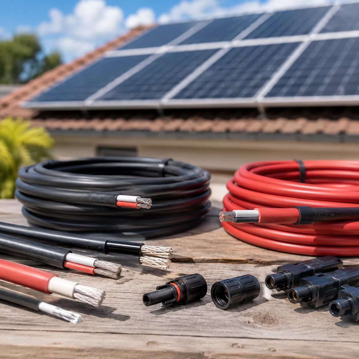
Rooftop PV Systems
Rooftop cable is exposed to direct sunlight, high surface temperatures and sharp module-frame edges. The selected cable needs the required UV rating, temperature performance and mechanical protection.
Cable clips and supports should keep the cable away from roof surfaces, drainage paths and sharp metal edges.
Ground-Mounted Solar Farms
Ground-mounted arrays may include long string routes, cable trays, combiner boxes and underground transitions. The specification should separate exposed string cable from underground trunk cable instead of applying one cable description to the entire route.
Tracker Systems
Tracker movement can flex or pull the cable repeatedly. A standard fixed-installation approval does not automatically cover continuous dynamic movement. Confirm the permitted movement, bend radius, support arrangement and tested cable type.
Floating and High-Moisture Installations
A general moisture-resistant claim is insufficient for continuous or repeated water exposure. Floating PV projects should specify the water classification, immersion conditions, cable movement and connector sealing requirements.
Residential PV Arrays
Residential systems still require approved PV DC cable for exposed module and string connections. Ordinary indoor building wire should not replace solar cable in an exposed PV route unless the design, wiring method and local rules explicitly permit it.
Solar Cable Size Belongs in the Size Guide
Cable type and cable size answer different questions.
This guide explains what the cable is: its conductor, insulation, sheath, standard, voltage, temperature rating, UV performance and marking.
Cable sizing determines how much conductor area the project needs. The calculation depends on current, string voltage, route length, voltage drop, installation method, ambient temperature, cable grouping and connector compatibility.
Use the dedicated Solar Cable Size Guide for:
- 4mm² vs 6mm² vs 10mm² PV cable
- Current-carrying capacity checks
- Voltage-drop calculations
- Cable length examples
- Connector and terminal compatibility
- Temperature and grouping adjustments
The final size should come from the project calculation rather than a universal recommendation in a general solar cable specification article.
Surface Printing and Batch Traceability
The cable print should allow the buyer and installer to match the delivered cable to its technical documents.
For a B2B order, require the approved print legend to identify:
- Manufacturer or brand
- Cable designation
- Number of conductors and nominal size
- Rated voltage
- Applicable standard
- Authorized certification mark, when required
- Production year or batch code
- Sequential meter marking, when specified
- Environmental or fire claim supported by the relevant test
Before mass production, approve a digital print proof or physical sample. After production, compare the cable legend with the reel label, packing list, certificate and test report.
Our Cable Jacket Markings Guide explains how to review voltage formats, conductor codes, standards, certification marks and production traceability in more detail.
Solar Cable Installation Checks
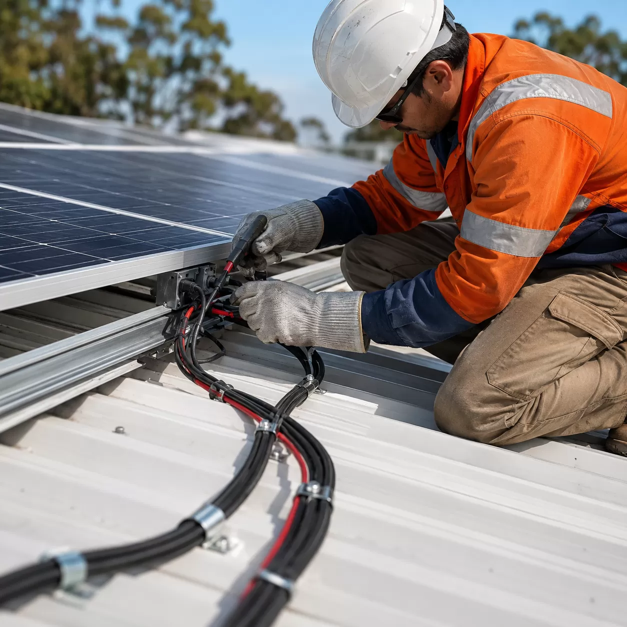
The correct cable can still fail if the installation damages the sheath or creates a poor connection.
Protect the Cable From Sharp Edges
Use approved clips, grommets or edge protection where the cable crosses module frames, tray openings or metal supports. Do not allow the sheath to rub against unfinished metal.
Follow the Stated Bend Radius
Use the minimum bend radius from the manufacturer’s data sheet. Tight bends can deform the insulation, stress the conductor and affect connector alignment.
Check Connector Compatibility
Match the conductor size and cable outer diameter to the connector’s approved range. A connector gland that is too large or too small may not seal correctly.
Do not assume that visually similar connectors from different brands can be mixed. Confirm the approved connector combination and crimping tools.
Control Cable Movement and Sagging
Keep cables off roof surfaces and away from standing water. Provide enough slack for thermal movement without leaving loops that can catch debris or move in the wind.
Inspect the Marking Before Installation
Confirm the cable designation, size, voltage and standard before cutting or pulling the cable. Record reel and batch information for project traceability.
B2B Solar Cable RFQ Checklist
Send the following information when requesting a quotation:
| RFQ field | Information to provide |
|---|---|
| Project country | Destination market and local approval requirements |
| Cable designation | PV1-F, H1Z2Z2-K or another specified type |
| Standard | EN 50618, IEC 62930, TÜV 2 PfG 1169 or project-specific requirement |
| Conductor | Tinned copper, conductor class and resistance requirement |
| Cable size | Final size from the project calculation |
| Voltage marking | Required AC and DC legend |
| Insulation and sheath | Required cross-linked compound and halogen requirement |
| Temperature | Normal conductor rating and any project-specific limits |
| Environment | Rooftop, ground mount, conduit, burial, water exposure or tracker movement |
| Color | Red, black or approved custom color |
| Surface print | Brand, type, size, voltage, standard, batch and meter marking |
| Certification | Certificate, test report and factory scope required |
| Connector data | Accepted conductor size and cable diameter |
| Length | Total quantity and required coil or drum length |
| Packaging | Coil, reel, wooden drum, pallet and export-label requirements |
For a technical quotation, send this information through the KingForYou Cable contact page.
Frequently Asked Questions About Solar Cable
Are PV1-F and H1Z2Z2-K the Same Cable?
No. They refer to different specification systems. PV1-F is associated with TÜV 2 PfG 1169, while H1Z2Z2-K is the harmonized designation under EN 50618. A project engineer or approving authority should confirm any substitution.
Is Every H1Z2Z2-K Cable Compliant With IEC 62930?
Not automatically. H1Z2Z2-K identifies the EN 50618 construction. If the project also requires IEC 62930, check that the product documentation and certificate state IEC 62930 separately.
Does H1Z2Z2-K Use Tinned Copper?
A compliant H1Z2Z2-K construction uses a flexible Class 5 tinned copper conductor. Confirm the conductor material, resistance and size range in the certificate and data sheet.
Can Solar Cable Operate Continuously at 120°C?
No. The normal continuous maximum conductor temperature is 90°C. The 120°C conductor value is limited to a cumulative period of 20,000 hours under the standard conditions.
Does UV Resistance Mean the Cable Can Be Buried Directly?
No. UV resistance covers sunlight exposure. Direct burial requires separate confirmation of burial suitability, mechanical protection, water performance and local installation rules.
What Solar Cable Size Should I Choose?
Select the size after checking current, voltage drop, route length, temperature, grouping and connector fit. See the Solar Cable Size Guide for the calculation process and 4mm², 6mm² and 10mm² comparisons.


